Boat radar reflectors: selection, fitting and limits
How to assess RCS, X and S bands, standards and test evidence before choosing a radar reflector, installing it correctly and managing its limits.
In brief
Choose a radar reflector by checking X- and S-band coverage, all-angle and heel performance, the declared standard, required orientation and safe mounting height—not just peak RCS. An active RTE can give a more consistent return but depends on electrical power. No device guarantees detection, so lookout and timely collision-avoidance action remain essential.
Article outline
A radar reflector is best understood as a visibility aid whose performance changes with geometry, heel and installation. It cannot make a yacht or motorboat reliably conspicuous in every sea state, but a well-chosen unit can improve the chance that a ship’s radar receives a usable, repeatable return.
This guide turns the available evidence into an equipment decision and an inspection routine. The legal references are international SOLAS provisions interpreted in UK guidance; owners must still check flag-state, local and commercial-vessel rules that apply to their own craft.
What the receiving radar actually sees
Radar Cross Section, abbreviated RCS, is an equivalent measure of how strongly a target sends microwave energy back toward the radar. It is not the boat’s deck area, and it does not remain fixed as bearing, heel, construction and orientation change. A compact device can therefore produce a high return in one direction and a poor return a few degrees away.
Detection is also controlled by the observing ship. MCA guidance identifies radar quality and height, range, target shape and aspect, waves and atmospheric conditions as relevant variables. Commercial shipping uses X-band equipment around 9 GHz and S-band equipment around 3 GHz, so a claim that does not identify the band tells only part of the story.
The practical target is consistency, not a spectacular laboratory peak. The loss of the yacht Ouzo in 2006 made that issue concrete: the MAIB investigation found that the bridge team on Pride of Bilbao did not see or otherwise detect Ouzo until effective avoiding action was no longer possible. That finding cannot prove what one different reflector would have changed, but it supports treating radar conspicuity as one independent safety layer.
Reading the SOLAS requirement without shortcuts
SOLAS Chapter V Regulation 19.2.1.7 says that a ship below 150 gross tonnage shall, if practicable, have a radar reflector or another means enabling detection by ships using radar at both 9 and 3 GHz. “If practicable” calls for a reasoned installation decision; it is not evidence that any token reflector is adequate. Whether the provision is directly enforceable on a particular boat depends on jurisdiction and operation.
MCA MGN 349 Amendment 1 advises craft under 15 metres to consider the most effective and appropriate reflector for their circumstances. It reproduces the basic IMO MSC.164(78) performance levels: at least 7.5 m² RCS at X band and 0.5 m² at S band when mounted at least 4 metres above the water. That response should cover a total of at least 280° in azimuth, with restrictions on wide nulls, and remain available through 10° of heel for power craft and low-heel multihulls or 20° for other vessels.
Those figures are procurement questions, not a detection promise. Ask for test evidence at both bands, the response around the full azimuth, the allowed nulls and the performance at heel. MGN 349 points to ISO 8729-1:2010 for passive reflectors and explains that compliant equipment can be physically difficult to fit on boats below 15 metres, making the documented compromise especially important.
Passive reflector and active enhancer trade-offs
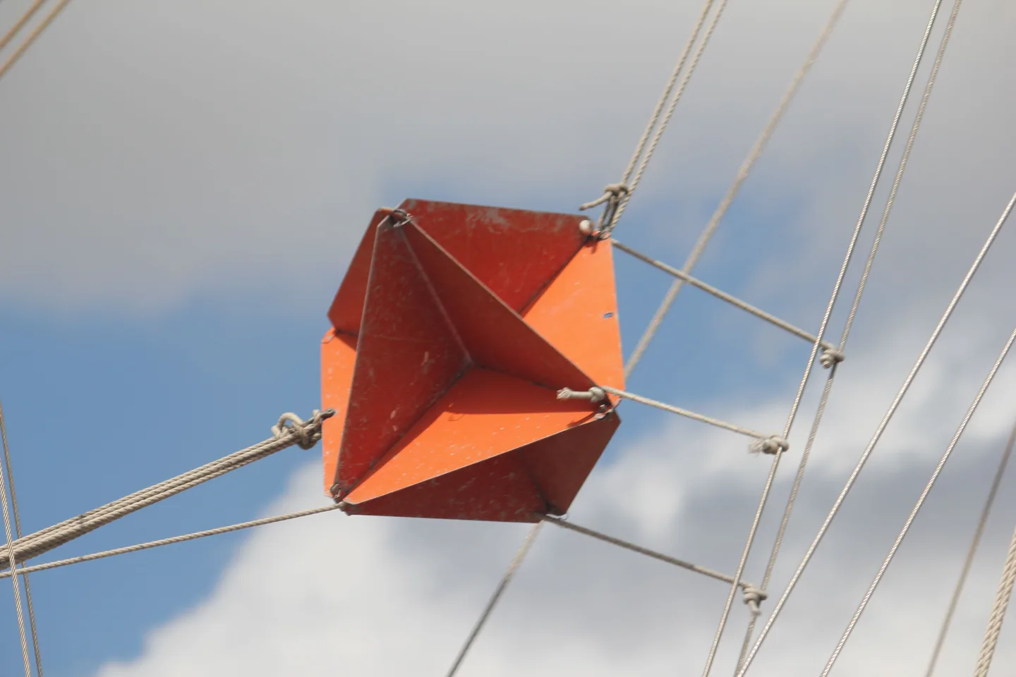
A passive reflector needs no electrical supply. Its internal geometry redirects part of an incoming radar signal, which makes the installation electrically simple but can demand considerable physical volume. Orientation errors, nearby rigging and heel may expose weak sectors in its response.
An active Radar Target Enhancer, or RTE, receives a radar pulse, amplifies it and transmits a reply. MCA guidance says this can provide a larger equivalent RCS from a smaller package and a stronger, more consistent display response. The price of that advantage is dependence on power, wiring and electronics that must be protected and tested.
Band coverage is a decisive specification. X-only and dual X/S-band enhancers exist, and an X-only RTE will not answer an S-band radar that a ship may use in heavy rain. Batoo analysis therefore ranks verified band support, heel performance and test evidence ahead of convenience, before considering weight aloft, electrical load and fault indication.
For offshore use, two different principles may be attractive: a competent passive unit remains available after an electrical failure, while a dual-band active enhancer may supply a more consistent return when powered. That is a design option, not a universal prescription. A marine electronics or rigging professional should assess separation, structure, stability and installation instructions rather than assuming that two devices automatically create useful redundancy.
What the QinetiQ measurements can and cannot prove
The MAIB-commissioned QinetiQ study measured nine reflectors at 9.41 GHz in a controlled environment. It sampled azimuth from 0° through 360° at several elevation angles, allowing the shape and continuity of the response to be compared. The report expressly limits its reach: an anechoic-chamber comparison cannot include every radar setting, sea-clutter condition, target aspect or propagation effect found offshore.
Its lasting lesson is how misleading a peak number can be. Tested reflectors could show strong lobes separated by nulls where very little energy returned; as a boat changes course or heels, the observing radar moves through those lobes and gaps. In the tested octahedral example, the “catch rain” orientation lowered the largest peaks but produced a more even average response over changing elevation.
The named products and historic prices in that report should not be used as a current shopping list. Designs, manufacturing and model names can change, and the study’s direct measurements were X-band only. Use the research to frame questions, then require evidence for the exact current product and declared standard.
Installation height is only one variable
MGN 349 recommends following the manufacturer’s orientation and mounting the reflector as high as practicable, ideally at least 4 metres above the water. It associates that arrangement with potential minimum detection ranges of 5 nautical miles for X band and 3.7 nautical miles for S band. “Potential” matters: those numbers are conditional guidance values, not a warranty for a particular ship, radar setting, sea or weather state.
A sailing installation must preserve the tested orientation while avoiding sails, halyards and standing rigging. A motorboat installation must consider masking by the cabin, mast and other antennas, as well as vibration and service access. Weight and windage aloft also affect structure and possibly stability, which is why the MCA recommends professional input where structural, performance or stability concerns remain.
An observation exercise with another vessel can reveal a gross installation problem, but it cannot certify RCS. Batoo suggests recording the exact model, standard, measured height and orientation, then asking a competent radar operator to observe the craft across several bearings and realistic attitudes. Log range, sea state and radar band; a single bright paint proves neither full-angle coverage nor standards compliance.
Build the reflector into the maintenance plan
At each seasonal inspection, check attachment points, orientation marks, cracks, water ingress, corrosion and deformation. For an active enhancer, add supply voltage, fuse, connectors, current draw and any built-in status indication specified by the maker. Repeat the inspection after rig work, a hard impact or any event that could twist the bracket.
Keep the manual, test declaration, wiring diagram and inspection record with the vessel’s technical file. If the model or required mounting position cannot be identified, its performance should be considered unresolved rather than inferred from the shape of the casing. Replacement is a rational outcome when traceability has been lost.
Most importantly, radar enhancement does not replace a proper lookout or collision-avoidance action. MCA guidance warns that a small craft may still fail to appear clearly even with a reflector or RTE and recommends rehearsing the response to collision risk. Navigation lights, sound signals, visual watch, AIS where carried and timely manoeuvring remain separate barriers; the reflector supports that system but never confirms that another bridge has seen you.
Sources and references
Sources consulted and references retained to verify data and context.
- MGN 349 (M+F) Amendment 1: Navigation safety—carriage and use of radar reflectors on small vesselsUK Maritime and Coastguard Agency · 2022-10-04
- Performance Investigation of Marine Radar Reflectors on the MarketQinetiQ for the Marine Accident Investigation Branch · 2007-03-27
- Sinking of sailing yacht Ouzo after encounter with Pride of BilbaoUK Marine Accident Investigation Branch · 2007-04-12
- Radar Reflectors—Safety EquipmentRoyal Yachting Association
Continue reading
406 MHz EPIRB and PLB: choosing, registering and testing
September 27, 2026 · 7 min read
Navigation lights: inspect and test them aboard
September 26, 2026 · 7 min read

Boat reboarding ladders: test them from the water
September 25, 2026 · 7 min read